 button from the
 During solution the model is loaded with a combination of factored Load Categories and/or Basic Load Cases, both of which are defined on the Basic Load Cases Spreadsheet. These combinations, load factors, and other parameters are defined on the Load Combinations Spreadsheet. Most standard load combinations are included in the program. See Solution to learn how to solve load combinations.
To Add Load Combinations Manually
To Add Auto-Generated Building Code Combinations
button from the Note
 button on the Window Toolbar.
 button
 Note
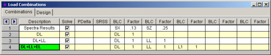
The Load Combinations Spreadsheet records the combinations of
loads for solution and may be accessed by selecting Load Combinations
on the
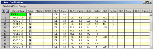
The first field, the Description, is strictly for the user's reference. Enter any descriptive label you wish and it may be displayed with the results when the combination is solved.
The next three fields are for options that apply to each load combination.
The Solve
box is used to indicate which combinations should be included
The P-Delta entry is used to enable an analysis of member secondary effects. See P-Delta Analysis for more information.
Note
The SRSS entry is used to combine response spectra results by the Square Root of Sum of Squares. See SRSS Combination of RSA Results for more information.
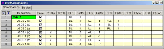
The next eight pairs of fields (BLC, Factor) are for defining what loads are to be part of the combination, along with factors for each. Select load categories from the drop down lists in the Category columns of the spreadsheet. The following are the entries you can use in the BLC field:
| Entry | Description |
|---|---|
|
Number |
Entering a number includes that particular Basic Load Case, I.e. enter “3" for BLC 3 |
|
Category |
Enter a category code such as DL, LL, etc to include all loads in that category |
|
Lnn |
Enter “Lnn” to nest the loads from another combination, where “nn” is the number of the other combination, i.e. “L3" means include all loads from load combination 3. |
|
Mnn |
Use this entry to include a moving load where “Mnn” is the moving load tag from the moving load spreadsheet |
|
Sn |
Includes response spectra results for the global direction “n”, I.e. enter “SX” to include response spectra results calculated in the global X direction, “SY” for global Y , etc. |
|
Tn |
Use this entry to include a time history load where “Tn” is the time history load tag from the Time History Loads spreadsheet |
Enter in the Factor field a multiplier to be applied to the loads being included.
You may also use the ![]() button in the BLC cell to help you specify the
loads. Choose from load categories, basic load cases, or spectral results or
moving loads from the drop-down lists.
button in the BLC cell to help you specify the
loads. Choose from load categories, basic load cases, or spectral results or
moving loads from the drop-down lists.
The first field, the Description, is strictly for the user's reference. Enter any descriptive label you wish and it may be displayed with the results when the combination is solved.
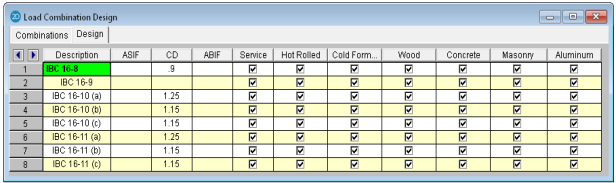
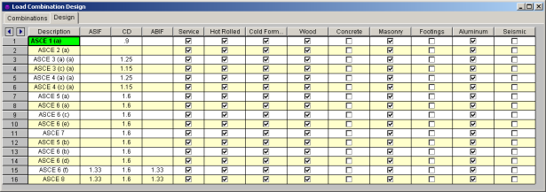
The ASIF column is used to set the allowable stress increase factor used for both the AISC: ASD code checking and ACI 530 ASD (masonry allowable stress design). See Allowable Stress Increase regarding its usage for Hot Rolled Steel.
The CD factor is the load duration factor and is only necessary for NDS timber design using ASD (see Load Duration Factor). Note: this is KD for Canadian (CSA O86) wood design.
The lambda factor is the time effect factor and is only necessary for NDS timber design using LRFD (see Time Effect Factor).
The Service check box is used in the following applications:
The results from
response spectra analyses in the X and Y direction may also be included
in the load combinations. Remember, when you perform a response
spectra analysis (RSA), you specify in which global direction the spectrum
is applied.
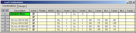
To include the RSA results for a particular direction in a load combination, enter "Sn" in the BLC field, where n is the global direction. Suppose you wanted to include X direction RSA results, you would enter SX in the BLC field. You would enter SY for Y direction RSA results. Also be sure to put the RSA Scaling Factor for the RSA results in the Factor field. You can have more than one RSA entry in a load combination.
Note
This is used to cause orthogonal RSA results in the combination to be summed together using an SRSS (Square Root of Sum of Squares) summation. This gives a good approximation of MAXIMUM responses but it also causes all the RSA results to be positive.
You may choose from the options by clicking
on the ![]() button. The entry is “+”
or “-” to indicate whether the combined RSA results are to be added (+)
or subtracted (-) from the other loads in the combination.
button. The entry is “+”
or “-” to indicate whether the combined RSA results are to be added (+)
or subtracted (-) from the other loads in the combination.
Note
Moving loads are included in your analysis by referencing them on the Load Combinations spreadsheet. For example, to reference moving load number “n” you would enter “Mn” in one of the BLC fields, and then also enter the corresponding BLC factor. The moving load numbers are shown for each moving load on the Moving Loads spreadsheet.
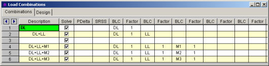
You are allowed only 10 BLC's per load combination, which may not be enough. For this reason you can define "combinations of load combinations". This means if you need more than 8 BLC entries in a single combination, you can define the needed BLC's and self-weights over several load combinations and then pull these combinations together into another load combination.
Entering "Lnn" in the BLC field means include all the BLC entries (with their factors) from Load Combination "nn". For example, say Load Combination 4 has "L1" entered for one of its BLC's. This specifies to include all the BLC's (with their factors) entered in Load Combination 1 as part of Load Combination 4 (this includes self-weight and RSA entries as well). The flags for Load Combination 1 (i.e. Solve, PDelta, and SRSS entries) apply only to Load Combination 1 and will not be used when Load Combination 4 is solved.
Also, the factor we enter with the "Lnn" entry will be applied to the BLC factors entered for LC nn. Thus, if we enter "L1" with a factor of "0.9", we're including 90% of the BLC entries of Load Combination 1.
Note
Entering a value/factor in the field labeled ASIF (Allowable Stress Increase Factor) indicates that the load combination should be treated as a wind/seismic load combination.
If AISC 9th Edition ASD code checking is selected, the allowable stress increase factor entered in this field is applied to this load combination.
The P Delta field
is used to perform a P-Delta calculation for that load combination. You
may choose from the options by clicking on the ![]() button.
A blank field indicates no P-Delta analysis, Y indicates that a
P-Delta analysis is to be performed for the combination.
button.
A blank field indicates no P-Delta analysis, Y indicates that a
P-Delta analysis is to be performed for the combination.
You may also perform a compression only P-Delta analysis. Invoke this option by putting a C in the P Delta field. See P-Delta Analysis for more information.
Note
For Wood design, the load duration factor (CD) is entered in the CD field on the row that the particular CD factor applies to. Different load combinations would have different CD factors. For example, per the NDS code, a load combination that had only dead load, would have a CD factor of "0.9", while another combination that was comprised of dead load plus wind load would have a CD factor of "1.6".
The CD factor will only be applied to wood code checks on wood members. "Wood" members are those members whose material properties are defined on the Wood tab of the Material Properties Spreadsheet.
Note
Major portions of the load combinations
that are specified by building codes are included and may be applied to
the model for solution. These combinations may be inserted
by selecting the button from the
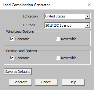
The LC Region refers to the various regions supported by the program (U.S., Canada, India, British, et cetera).
The LC Code refers to the actual code used to build the load combinations. For the United States, there are a number of different codes that could be used to build load combinations. If the only option is Sample, that means that no load combinations have been input for that region. See Customizing the Load Combination Generator for more information on how to add or edit combinations for that region.
The Wind Load Options specify how detailed the generated wind load combinations should be.
The Reversible option generates two combinations for each wind load, one with positive load factors and one with negative load factors.
The Seismic Load Options specify how complex the generated seismic load combinations should be.
The X and Z RSA option will use the spectral seismic loads (SX, SY, SZ) instead of the regular earthquake loading (ELX, ELY, ELZ).
When the Reversible box is checked, the program will generate every seismic load combination twice. Once with a positive load factor, once with a negative load factor.
The Save as Defaults button may be used to establish the current load combination generator settings as the defaults for future use. Clicking the Generate button will generate load combinations in the Load Combinations Spreadsheet based on the selected options.
The following loads are not generally included in the standard combinations but may be added by editing the combinations in the spreadsheet or by modifying the source document itself. For more information, see Customizing the Load Combination Generator below:
| Category Code | Description |
|---|---|
|
SX, SY, SZ |
Response Spectra Results |
|
TL |
Long Term Load |
|
HL |
Hydrostatic Load |
|
FL |
Fluid Pressure Load |
|
PL |
Ponding Load Category |
|
EPL |
Earth Pressure Load |
|
OL# |
Other Load Categories |
Note
The Load Combinations for each region are contained in an XML file which can be opened and edited using a standard spreadsheet program. An example of on of these XML files is shown below:
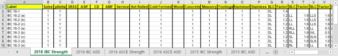
The name of the file itself becomes the name of the Load Combination Region that appears in the Load Combination Generator. Each XML file has a series of "worksheets" and the name of each worksheet will be the name of the Load Combination Code that appears in the Load Combination Generator. The user may add, edit or modify these documents to completely customize the available load combinations.
Note
The first row of each sheet is reserved
for the column headers. The recognized column headers are as follows:
Label,
Solve, pDelta, SRSS,
Other than Label and the BLC / Factor pairs, the user may omit columns. If a column is omitted, the default values will be used for those entries. The order of the column labels is optional except for pairs of BLC and Factor. For the program to correspond the Factor with correct BLC, the user should always provide BLC label PRIOR to the corresponding Factor. The user may insert blank columns or columns with other labels than described above. In those cases, the program omits those undefined columns.
Note